คุณกำลังมองหาอะไร?
Technical Design Guide | Sterile Filling Cleanroom
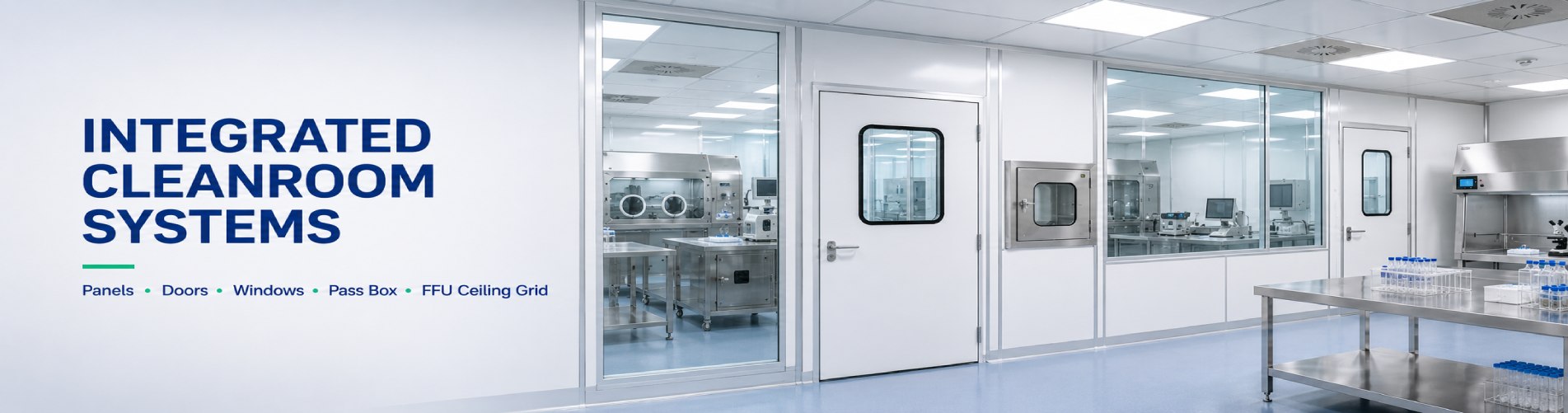
In sterile filling environments, wall panels and ceilings cannot be designed as separate packages. Pressure cascade, HEPA or FFU supply, return airflow, cleanable HPL surfaces, sealed penetrations and inspection access must work together to protect the contamination control strategy.
sterile filling cleanroom cleanroom wall ceiling integration FFU cleanroom ceiling cleanable HPL surface
| PressureControl leakage through walls, doors and ceilings. | FFU/HEPACoordinate supply, return and service access. | HPLReview cleanability and chemical compatibility. | Annex 1Support contamination control strategy. |
A sterile filling cleanroom is a controlled system, not a collection of panels, lamps and filters. The critical design question is how each wall, ceiling, door, return path and service penetration affects airflow direction, pressure stability, cleaning and qualification evidence.
System Integration
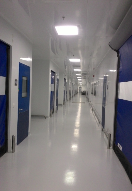
In sterile filling support spaces, wall panels define cleanable boundaries and pressure zones; ceilings carry HEPA diffusers, FFUs, lights, access panels, sensors and sometimes returns. If these systems are designed separately, the room can develop hard-to-clean ledges, unplanned penetrations, blocked service access or unstable pressure relationships.
EU GMP Annex 1 emphasizes contamination control strategy for sterile medicinal products. The room envelope should therefore support air cleanliness, cleaning, disinfection, personnel flow, material flow, maintenance and environmental monitoring as connected risks.
Wonclean design reviews should align wall elevations, ceiling grid, FFU or HEPA positions, door schedule, pressure cascade, HPL or coated surface finish, pass-throughs, returns and service penetrations before fabrication starts.
Pressure and Airflow
ISO 14644-1 classifies cleanrooms by airborne particle concentration, while ISO 14644-3 supports cleanroom test methods such as pressure difference, airflow and installed filter leakage tests. For sterile filling areas, these results are affected by the quality of envelope integration.
A pressure cascade can fail through small paths: ceiling perimeter gaps, unsealed access panels, door leakage, window frames, electrical boxes, pass-through frames or utility sleeves. These leaks may be invisible during construction but obvious during balancing and smoke visualization.
| Interface | Technical risk | Control method |
|---|---|---|
| Ceiling-to-wall joint | Leakage, residue pockets and difficult cleaning. | Use sealed, flush and inspectable perimeter details. |
| FFU or HEPA module | Filter bypass, uneven airflow or poor service access. | Coordinate ceiling grid, gasket, access and leakage test points. |
| HPL or cleanable wall surface | Cleaning chemistry can damage edges or joints. | Review finish, edge protection and disinfectant compatibility. |
| Door and window frame | Ledges, leaks and gasket wear affect pressure and cleaning. | Coordinate frame depth, sealant line, glazing and inspection access. |
FFU and HEPA Ceiling
Not every sterile filling room uses the same ceiling strategy. Critical Grade A protection may be provided by isolators, RABS or localized unidirectional airflow, while surrounding areas may use HEPA terminal supply or FFUs according to the facility's contamination control strategy. The ceiling layout must match the process risk, not a generic grid.
FFU or HEPA module locations should be coordinated with return paths, equipment heat loads, room shape, operator positions, door openings and environmental monitoring points. Service access is equally important: filter replacement and leakage testing should be possible without damaging cleanable wall and ceiling finishes.
For sterile filling suites, the ceiling should be reviewed together with the wall system so pressure boundaries, light fixtures, sprinkler or fire devices, sensors and cable penetrations do not create hidden contamination or leakage risks.
Cleanable HPL Surfaces
HPL can be a practical cleanroom wall surface when the grade, substrate, edge protection and installation detail match the cleaning program. The risk is rarely the middle of the panel; it is usually exposed edges, joints, penetrations, corners, coving and interfaces to doors or windows.
ASTM D1308 and ASTM D543 are useful references when discussing chemical exposure and material resistance. The project should still define actual disinfectants, contact time, wipe method and acceptance criteria.
For sterile filling support areas, HPL or coated panel systems should be smooth, non-shedding, compatible with cleaning chemistry and easy to inspect after repeated disinfection. Sealants and trims must be selected with the same care as the panel face.
Qualification Readiness
ISO 14644-4 links cleanroom design, construction and start-up. For sterile filling environments, the wall and ceiling package should produce qualification-ready records: panel layout, ceiling grid, HEPA/FFU schedule, pressure map, door and window schedule, penetration list, sealant data, surface material data and inspection points.
FDA aseptic processing guidance also emphasizes cleanroom control as part of CGMP expectations for sterile drug manufacturing. For engineering teams, this means the room should be testable and maintainable: airflow visualization, pressure checks, installed filter leakage tests where specified, recovery behavior and cleaning inspection should not be blocked by poor access.
The best design is one where the validation team can trace each cleanroom boundary decision back to a contamination-control reason.
Technical Fact Check
| Fact used | Source | Design implication |
|---|---|---|
| Cleanroom class is based on airborne particle concentration. | ISO 14644-1 | Wall and ceiling systems should support particle control and verification. |
| Cleanroom test methods include pressure difference and installed filter leakage testing. | ISO 14644-3 | Ceiling filters and room envelope details must be testable. |
| Cleanroom design and start-up should be coordinated. | ISO 14644-4 | Wall panels, ceiling grid, doors and services should be reviewed together. |
| Sterile manufacturing guidance requires contamination control thinking. | EU GMP Annex 1 | Envelope design should support CCS, cleaning and monitoring. |
| Aseptic processing guidance links cleanroom control to CGMP expectations. | FDA aseptic processing guidance | Room controls should be testable, maintainable and documented. |
| Surface chemical resistance should be tied to defined exposure conditions. | ASTM D1308 and ASTM D543 | HPL and coated surfaces should be checked against disinfectants and cleaning frequency. |
Referenced Standards
FAQ
Because pressure, airflow, cleaning, service access and leakage paths all cross the wall-ceiling boundary. Separate design can create gaps, ledges or inaccessible test points.
No. The ceiling strategy depends on process risk, Grade A protection method, background grade, isolator or RABS use, heat load, airflow pattern and maintenance plan.
They can be suitable when the HPL grade, substrate, edge protection, sealants and cleaning compatibility match the facility's disinfectants and inspection requirements.
Useful records include panel layout, ceiling grid, HEPA or FFU schedule, pressure map, door and window schedule, penetration list, material data, sealant data, installed filter tests and inspection records.
Wonclean Engineering Note
For sterile filling cleanrooms, wall panels and ceilings should be treated as one controlled envelope. The cleanroom will be easier to test, clean and maintain when pressure boundaries, FFU or HEPA positions, HPL surfaces, doors, windows and penetrations are coordinated early.
Useful Wonclean references: cleanroom wall system, cleanroom ceiling system, fan filter unit, cleanroom sandwich panel, cleanroom door, contact Wonclean.

 Room JT30151, Building 4, Area B, No. 925 Yecheng Road, Industrial Zone, Shanghai,China
 Info@wonclean.com
Allen@wonclean.com
Joy@wonclean.com
Info@wonclean.com
Allen@wonclean.com
Joy@wonclean.com
 +86 13671979988(Allen)+86 15950938878(Joy)


 บริการออนไลน์

